Coaxial Cable Insertion Loss and VSWR Testing for EMC Applications
In high-frequency RF engineering and Electromagnetic Compatibility (EMC) compliance testing, measurement accuracy depends on every component in the RF signal path. Low-loss coaxial cables are critical links in any test environment, yet they are often the most frequent point of failure. Over time, repeated bending, mechanical stress, thermal expansion, and connector wear degrade cable shielding and center conductors, leading to unexpected signal attenuation or impedance mismatches that can jeopardize CISPR, MIL-STD, and FCC compliance testing results.
Regularly validating your test leads for insertion loss (S21) and Voltage Standing Wave Ratio (VSWR / S11) ensures measurement repeatability and precision while preventing costly re-testing. This comprehensive technical guide details the standard procedure for verifying high-performance coaxial cable assemblies using a Vector Network Analyzer (VNA).
Why RF Cable Verification Matters in EMC Testing
A coaxial cable is the physical bridge between an antenna, probe, or device under test and the measurement receiver. Even a high-quality cable introduces insertion loss and reflection into the signal path. When a cable degrades, the degradation is often invisible: there is no visible damage, but the measurement results shift. This silent failure mode is particularly dangerous in EMC compliance testing, where a few decibels of unexpected loss can mean the difference between a pass and a fail.
Several factors accelerate cable degradation:
- Mechanical stress: repeated bending, especially near connector strain-relief boots, can fracture the center conductor or break shield continuity.
- Thermal cycling: expansion and contraction of dielectric and conductor materials shift impedance characteristics over time.
- Connector wear: repeated mating cycles erode plating and alter center-pin insertion depth, creating impedance discontinuities.
- Dielectric aging: prolonged exposure to high RF power or elevated temperatures can degrade the dielectric material, increasing attenuation.
Equipment Needed for Coaxial Cable Testing
Before initiating RF cable verification, assemble the following calibrated test equipment and ensure thermal stabilization across the setup:
- Vector Network Analyzer (VNA): Alternatively, a tracking generator paired with a spectrum analyzer and directional bridge or coupler can be used.
- Mechanical Calibration Kit: Open, Short, Load (OSL) precision standards matching the connector interface of the Cable Under Test (CUT).
- Precision Adapters and Torque Wrench: Low-reflection, grade-matched 50-ohm adapters and a calibrated torque wrench to prevent connector damage and ensure repeatable mating force.
- System Warm-up: Allow all test instruments to warm up for at least 30 minutes to stabilize internal phase-locked loops (PLLs) and source power outputs.
Step 1: Configure and Calibrate the VNA
Accurate cable loss and reflection measurements require proper vector error correction to eliminate the amplitude and phase effects of the test setup leads, adapters, and connectors.
Configure the Frequency Sweep
Define the VNA start and stop frequencies to encompass the full operating frequency range of the Cable Under Test (for example, 10 MHz to 18 GHz). Set the IF bandwidth (IFBW) to 1 kHz to balance dynamic range and sweep time.
Perform Full 2-Port Calibration (SOLT)
Output the rated RF power level for your test protocol. Connect the OSL standards directly to the reference planes of Port 1 and Port 2, executing a full 2-port Short-Open-Load-Thru (SOLT) calibration to normalize out system connector and adapter losses.
Verify the Error Correction Baseline
After calibration, confirm the system is performing as expected before connecting the CUT:
- Connect the precision 50-ohm load to Port 1. Confirm the return loss (S11) reads better than -30 dB across the full band.
- Connect a known high-performance reference cable across Port 1 and Port 2. Confirm insertion loss (S21) reads 0 dB plus or minus 0.1 dB.
Step 2: Measure Insertion Loss (S21)
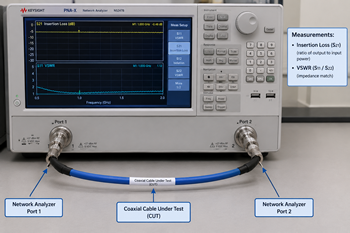
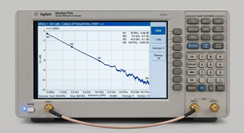
Insertion loss measures the total RF energy attenuated by the coaxial assembly through conductor resistance, dielectric absorption, and radiation losses.
- Connect the Cable Under Test (CUT) between Port 1 and Port 2 using a calibrated torque wrench to ensure consistent mating force.
- Display parameter S21 formatted in log magnitude (dB).
- Place active markers at key operational test frequencies across your band (e.g., 100 MHz, 1 GHz, 6 GHz, and 18 GHz).
Step 3: Measure Return Loss and VSWR (S11 / S22)
Voltage Standing Wave Ratio (VSWR) characterizes impedance discontinuities along the coaxial line, quantifying reflected power caused by internal mechanical defects or pin misalignments.
- Configure Trace 1 for S11 (Input Reflection) and format the trace to display VSWR (or Return Loss in dB). If using a full 2-port system, set Trace 2 to S22 (Output Reflection).
- Ensure the distant end of the cable is properly terminated into Port 2 or a precision 50-ohm load.
- Identify the maximum peak VSWR across the entire sweep range.
Step 4: Perform Mechanical Flex Testing
Static coaxial testing can mask intermittent physical breaks or shield degradation that occur only when cables are positioned during active EMI/RFI testing.
- While monitoring real-time S11 and S21 traces, apply gentle flexing near the connector strain relief boots on both ends of the cable assembly.
- Monitor the screen for amplitude spikes, phase jumps, or VSWR discontinuities. Sudden jumps in S11 indicate loose crimps, center conductor fractures, or deteriorating outer braid contact.
- Visually inspect mating faces, center pin insertion depths, threads, and dielectrics for signs of mechanical wear or contamination.
Step 5: Document Results for Compliance Tracking
To maintain ISO/IEC 17025 compliance and track cable degradation over time:
- Record ambient room temperature and relative humidity during measurement.
- Export full S-parameter datasets (S21, S11) in Touchstone (.s2p) format or save vector trace images.
- Log serial numbers, measurement dates, pass/fail status, and maximum recorded VSWR values directly into your equipment maintenance ledger.
Recommended Pass/Fail Guidelines for RF Test Cables
The following table summarizes typical pass/fail criteria for precision RF test cables used in EMC compliance testing. Always defer to your specific test standard and the cable manufacturer’s published specifications.
| Parameter | Typical Pass Criterion | Notes |
| Insertion Loss (S21) | Within manufacturer datasheet spec (dB/m or dB/100 ft) | Compare against cable model datasheet |
| VSWR (S11) | ≤ 1.25:1 (precision lab cables) | Up to 1.5:1 acceptable at microwave frequencies |
| Return Loss (S11) | Better than -30 dB (post-calibration baseline) | Verify with precision 50-ohm load |
| Flex Test Stability | No S11/S21 spikes > 0.2 dB during flexing | Indicates intermittent faults |
Frequently Asked Questions
What is insertion loss in a coaxial cable? Insertion loss, measured as the S21 parameter, is the amount of RF signal energy attenuated as it travels through a coaxial cable assembly. It accounts for conductor resistance, dielectric absorption, and radiation losses, and is typically expressed in decibels (dB). Higher insertion loss means more signal degradation.
What is an acceptable VSWR for RF test cables? For precision laboratory test cables used in EMC compliance testing, a VSWR below 1.25:1 is typically expected. At higher microwave frequencies (above 18 GHz), a VSWR up to 1.5:1 may be acceptable. Always confirm specific thresholds against your test standard and the cable manufacturer’s published specifications.
How often should EMC test cables be verified? EMC test cables should be verified before initial use, after any visible damage or performance anomaly, and at regular intervals as defined by your laboratory’s quality management system. Many ISO/IEC 17025 accredited labs perform cable verification quarterly or semi-annually, with additional checks after high-volume testing periods.
Why use a VNA for cable verification? A Vector Network Analyzer provides full S-parameter measurement capability, capturing both magnitude and phase of the reflected and transmitted signals. This enables full 2-port error correction (SOLT calibration), which removes the effects of adapters, test leads, and connector variability, resulting in the most accurate measurement of the cable’s true performance.
What causes high VSWR in a coaxial cable? High VSWR is caused by impedance discontinuities along the coaxial line. Common causes include connector wear or contamination, center conductor fractures, shield degradation from repeated bending, dielectric deformation, or pin misalignment at mating interfaces. Mechanical flex testing helps detect intermittent issues that static measurements may miss.
Why does flex testing matter for RF cables? Flex testing reveals intermittent cable faults that static S-parameter measurements cannot detect. By gently flexing the cable near connector strain reliefs while monitoring real-time S11 and S21 traces, engineers can identify loose crimps, broken center conductors, and deteriorating shield contact that only manifest when the cable is physically positioned during active testing.
